Public transport network vs. infrastructure network
The network is often represented on a background map, which describes the area served by public transport (e.g. city map). It is also common to show a projection of various parts of a PASSENGER TRIP on a map.
The map with its layers or spatial features is typically provided separately by a map server that integrates and renders geographical information system (GIS) data.
Transmodel provides a general mechanism to model the correspondence between different layers of spatial information, called a PROJECTION (for more information on PROJECTIONs see EN12896-2).
In order to display the PT layer data onto the map layer a projection as a sequence of spatial coordinates must be provided to the application. This can be done, for instance, by LINK PROJECTION of the ROUTE LINKs on INFRASTRUCTURE LINKs.
Schematic representation of the public transport network
A very simple representation of a PT network consists in drawing a schematic description of each SERVICE PATTERN on a straight line, with all SCHEDULED STOP POINTs marked on that line at the same distance from each other. This is a purely topological representation of a JOURNEY PATTERN (or a SERVICE PATTERN) as an ordered sequence of points.
Some additional information may be added to this simple representation, e.g. LINEs with which an interchange is proposed at particular SCHEDULED STOP POINTs may be indicated or FARE SECTIONs.
If the LINE includes more than two ROUTEs, in particular when there are diverging branches, other linear forms are necessary. A SCHEMATIC MAP (See EN12896-1) can be used to provide a coloured line-based representation, including branches.
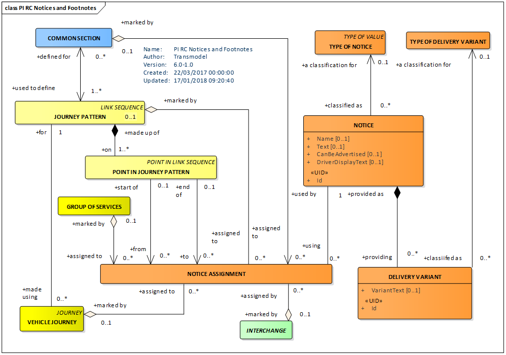
Most of the lines of a network will have an advertised destination, generally known to the passengers and displayed on the vehicle (i.e. on the headsign) and also used in the information material. This destination is not necessarily the name of the final destination (e.g. the name of the last POINT IN JOURNEY PATTERN). Such headings may be described consistently by the entity DESTINATION DISPLAY (see Line & Route MODEL, EN12896-2), which may also have different variants for use in different contexts and media (DELIVERY VARIANT).
The entity NOTICE allows human readable text annotations describing exceptions and other arbitrary conditions to be provided for informational purposes as attachments for a LINE, a JOURNEY PATTERN, SERVICE JOURNEY, FARE PRODUCT, etc. The information may be usable for passenger or driver information.
A timetable is an end product of the scheduling process. It gives the scheduled PASSING TIME (in general, departure times) for all VEHICLE JOURNEYs, on all SCHEDULED STOP POINTs, for one or possibly several DAY TYPEs.
Although the ‘timetable’ is a very well-known and important concept, it is not described in the data model as an inherent entity, because it contains only derived data; a TIMETABLE FRAME represents such an assembly and can be used to organise journeys into named sets with a particular validity that can be rendered in tabular form. The process of computing timetable information (in particular the passing times) is described in detail in EN12896-3. The GROUP OF JOURNEYs element can be used to create subsets of journeys with similar properties (e.g. same direction, service pattern, etc) to guide the efficient rendering of a timetable into a tabular format.
Passing times
Any theoretical PASSING TIME at a point may be derived from the underlying scheduling information. However, in real implementations, this data will often be pre-calculated and stored.
The PASSING TIMEs that are the results of the scheduling process for publishing in a timetable are called TIMETABLED PASSING TIMEs (see EN12896-3).
The PASSING TIMEs that are computed on a specific OPERATING DAY are called DATED PASSING TIME. This entity has several subtypes, described in EN12896-3:
- TARGET PASSING TIME, the latest official plan for a DATED VEHICLE JOURNEY, on a POINT IN JOURNEY PATTERN;
- ESTIMATED PASSING TIME, a forecast for a MONITORED VEHICLE JOURNEY, on a POINT IN JOURNEY PATTERN;
- OBSERVED PASSING TIME, recorded for a MONITORED VEHICLE JOURNEY, on a particular POINT.
Calls
When organising data for efficient exchange and presentation to the passenger, it is sometime useful to rearrange it in views that may be denormalised, or that may include additional derived data.
In particular a CALL, defined as a view that brings together data relating to the individual visit to a POINT IN JOURNEY PATTERN in a VEHICLE JOURNEY assembles information held variously on a POINT IN JOURNEY PATTERN and related entities, grouping planned estimated and observed arrival times and departure times in convenient CALL PARTs, and referencing ancillary information such as the DESTINATION DISPLAY and NOTICEs for the POINT IN PATTERN (for further details see EN 12896-3).
Frequency-based services
Where services are very frequent (typically less than every 10 minutes) it is often the practice not to publish specific passing times for the stops on a timetable, but rather simply to indicate a frequency of service (for example, “every 5-8 minutes”). This may be represented by a TEMPLATE SERVICE JOURNEY which gives the service pattern that is followed, and a FREQUENCY GROUP that gives the expected intervals – see EN12896-3.
Modern computer-aided travel tools assist potential travellers in preparing their trips, particularly in answering specific TRIP REQUESTs. Such a trip planning function identifies the origin and destination places of an intended trip and proposes one or several TRIP solutions.
The Trip Description Models describe the trips and fares that passengers may make on transport networks, in particular public transport, but possibly also including legs made by car, cycle, walking, ride sharing or other private modes.
A TRIP is defined as a part of a TRIP PATTERN describing the movement of a passenger from one PLACE of any sort to another. A TRIP may consist of one or more consecutive LEGs having some common characteristics.
A TRIP PATTERN describes complete spatial movement of a passenger from an origin PLACE to a destination PLACE, using public transport vehicles and other modes, including possibly walking and non-public transport legs, done for a specific TRIP REASON.
A TRIP PATTERN may consist of one or more consecutive TRIPs.
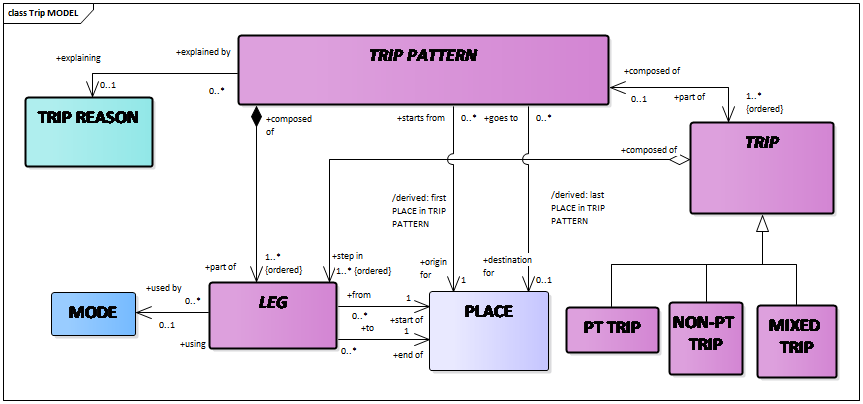
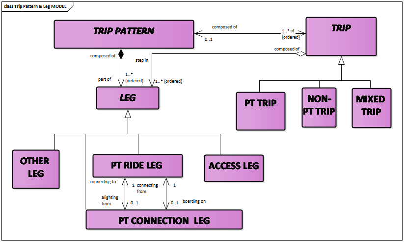
A LEG is the principal component of a TRIP PATTERN.
Each LEG describes a movement of a user in a single vehicle, or using a single other mode such as walking, cycling, or driving. LEGs may be of different types (PT RIDE LEG, ACCESS LEG, PT CONNECTION LEG, OTHER LEG, etc.) depending upon the mode of transport used to make them. In particular:
- A PT RIDE LEG is that part of a passenger trip taken on a single PT vehicle, from one SCHEDULED STOP POINT to another. A PT RIDE LEG is carried out on only one JOURNEY PATTERN;
- An ACCESS LEG describes a non-public transport LEG made between an arbitrary origin or destination PLACE and a SCHEDULED STOP POINT, when accessing public transport.
- A PT CONNECTION LEG describes details of the interchange made from one SERVICE JOURNEY to another over a CONNECTION between two SCHEDULED STOP POINTs.
- An OTHER LEG can be used to describe a leg on another mode of transport (for example by car) making up a trip, from an origin PLACE to a destination PLACE. The origin and destination may be a SCHEDULED STOP PLACE or some other type of place such as an ADDRESSABLE PLACE, POINT OF INTEREST, etc.
The overall Trip Model is as follows:
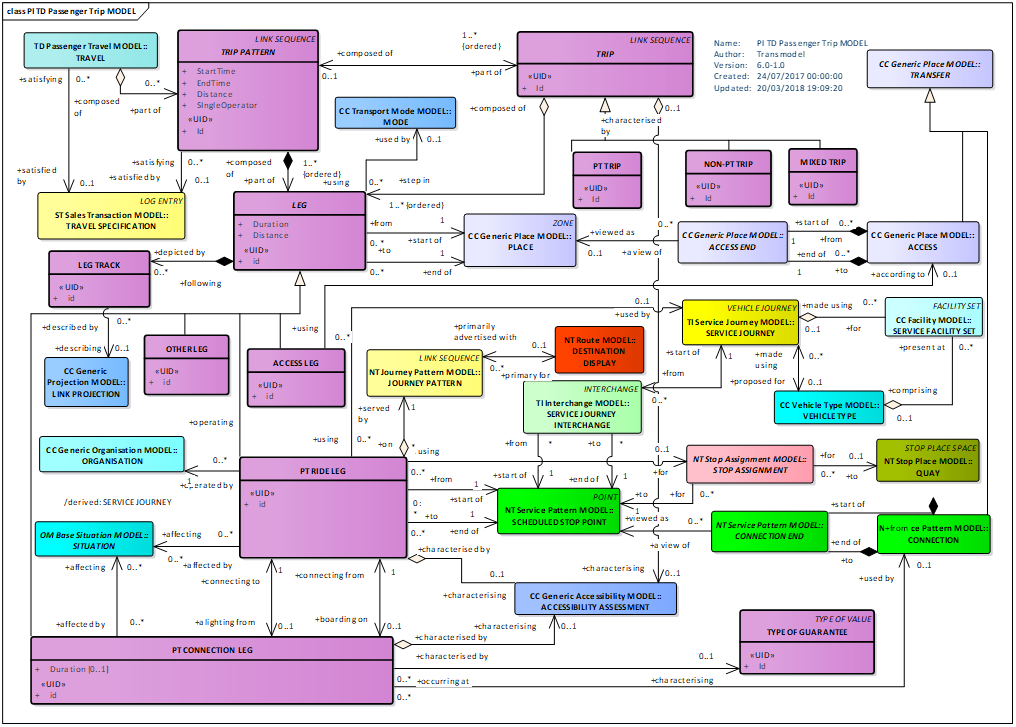
A PT CONNECTION LEG is a part of a TRIP PATTERN corresponding to the movement of a passenger transferring from one SERVICE JOURNEY to another, made over a CONNECTION from one SCHEDULED STOP POINT to another, and possibly following a specific NAVIGATION PATH (a designated path between two places, see EN12896-2).
The PT CONNECTION LEG may be characterised by the type of guarantee offered for a given connection.
PATH GUIDANCEs can be used to provide step by step instructions for following the path through the PT CONNECTION LEG, if necessary, referring to signage modelled as part of the SITE description, as well as headings, turn instructions and level changes computed from the path.
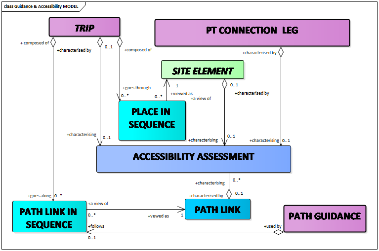
PATH LINK IN SEQUENCE is a step of a NAVIGATION PATH indicating traversal of a particular PATH LINK as part of a recommended route (for more details see Site Model, Path & Navigation Path Model provided in EN 12896-2).
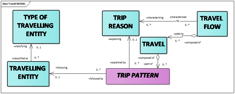
A passenger TRIP may be a part of a wider pattern of TRAVEL, made for different reasons. For example, a passenger might make a trip to deliver their children to school, then another to proceed to work. The wider pattern can be captured as a TRAVEL, a set of trips for a given TRAVELLING ENTITY, made for a specific TRIP REASON.
A TRAVEL may also be used to assemble a collection of alternative TRIP PATTERNs that all satisfy the same TRAVEL SPECIFICATION, so as to present a selection of alternative routes to a customer.
Data from multiple TRAVEL instances can be summarised as a TRAVEL FLOW for statistical purposes.
Some examples of simple travel specifications:
- Simple trip from one bus stop to another
TRIP PATTERN [TRIP REASON= go to work] is composed of a PT TRIP composed of one PT RIDE LEG [MODE = bus] - Walk to a bus stop, catch the bus, walk to the shop
TRIP PATTERN [TRIP REASON= go shopping] is composed of a PT TRIP composed of an ACCESS LEG [MODE = walk] followed by a PT RIDE LEG [MODE = bus], followed by an ACCESS LEG [MODE = walk]. - Walk to the station, catch the train, cross town in a taxi, take the second train, walk to the meeting centre may be represented by a TRIP PATTERN [TRIP REASON= business trip] composed of:
a PT TRIP composed of an ACCESS LEG [MODE = walk], a PT RIDE LEG [MODE = rail], an ACCESS LEG [MODE = walk]
a NON-PT TRIP composed of an OTHER LEG [MODE = taxi]
a PT TRIP composed of an ACCESS LEG [MODE = walk], a PT RIDE LEG [MODE = rail], an ACCESS LEG [MODE = walk].
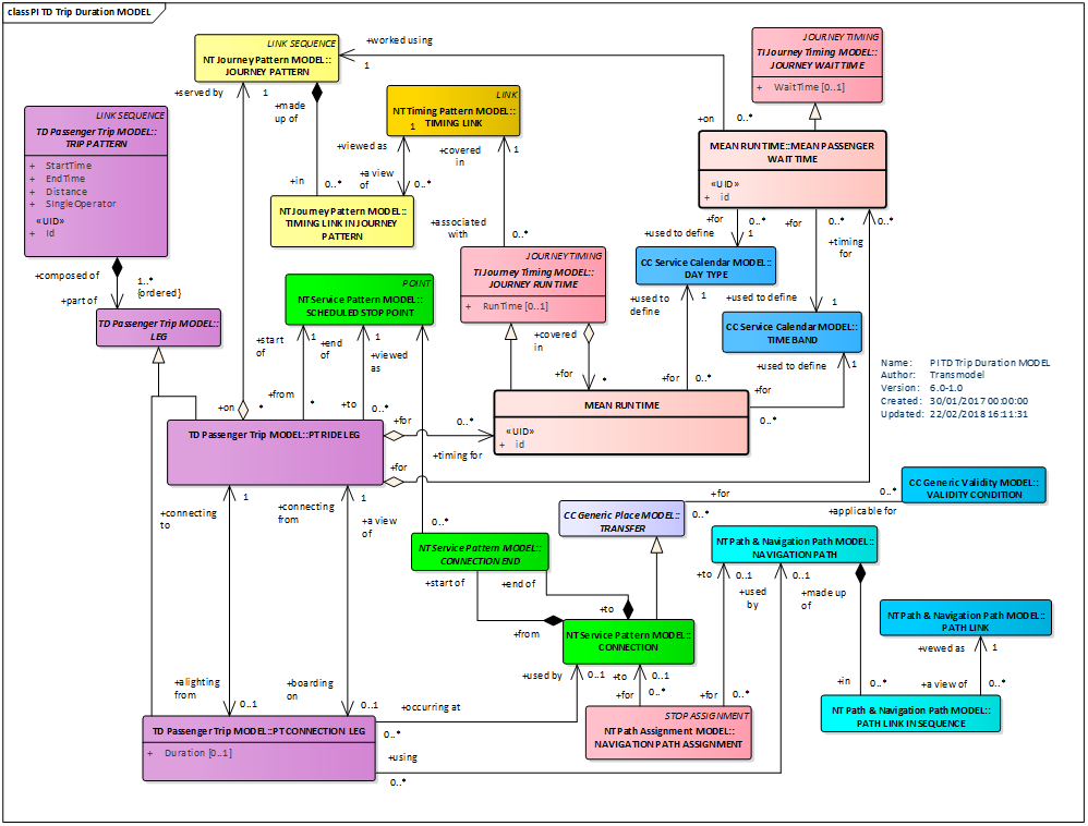
The TRIP DURATION Model specifies how long a trip will take. It provides additional information for the Passenger Trip Model.
A mean PASSENGER RUN TIME can be specified for the time to travel each leg of a PT TRIP, and a MEAN PASSENGER WAIT TIME can be specified for the average wait time at each stop. These can be used to compute an overall travel time.
Where a specific VEHICLE JOURNEY is cited an exact time can be calculated from the PASSING TIMES.
Several concepts in the diagram below are presented and discussed in detail in EN 12896-3.
It may be useful to monitor the actual status of the service in real-time against the planned TRIP in order to be able to inform the passenger of any delays.
TRIP PATTERN MONITORING is the action of monitoring a passenger movement in real-time to provide progress information for a passenger.
A MONITORED TRIP describes the monitoring of an individual planned TRIP. It is made up of MONITORED LEGs; each MONITORED LEG can relate a specific PT RIDE LEG to a specific MONITORED VEHICLE JOURNEY in order to derive progress information.
Observed and estimated PASSING TIMEs may be represented for the user as MONITORED LEG CALLs for each stop of interest on the journey. The MONITORED LEG CALLs may have separate MONITORED LEG PARTs for the arrival (MONITORED LEG ARRIVAL) and departure (MONITORED LEG DEPARTURE) steps.
MONITORED TRIP may itself be part of a sequence of trips constituting a MONITORED TRIP PATTERN.
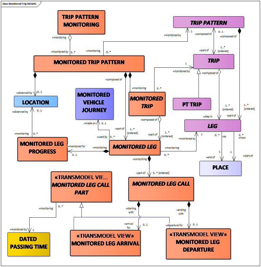
MONITORED LEG PROGRESS provides the relative progress of a passenger along a LEG (current distance along a LEG, time at which LEG started or /ended, etc).
To describe the fares available for a trip, the Passenger Fare Offer Model includes a PT FARE OFFER, defining an available fare for a specific PT RIDE LEG in a PT TRIP or for the whole PT TRIP, or for the whole TRIP PATTERN. The fare may be restricted to particular products and conditions as described by SPECIFIC PARAMETER ASSIGNMENTS, related to the OFFERED TRAVEL SPECIFICATION (a set of parameters giving details of the intended consumption of access rights (e.g. origin and destination of a travel, class of travel, etc.)).
The diagram below reminds several concepts defined and discussed in EN12896-5, in particular:
- TARIFF representing a particular instance of a fare structure;
- VALIDABLE ELEMENT: a sequence or set of FARE STRUCTURE ELEMENTs, grouped together to be validated in one go;
- FARE PRODUCT: an immaterial marketable element (access rights, discount rights, etc.), classified by the payment method and the account location: pre-payment with cancellation (throw-away), pre-payment with debit on a value card, pre-payment without consumption registration (pass), post-payment etc.;
- SALES OFFER PACKAGE: a package offered for sale as a whole, consisting of one or several FARE PRODUCTs.
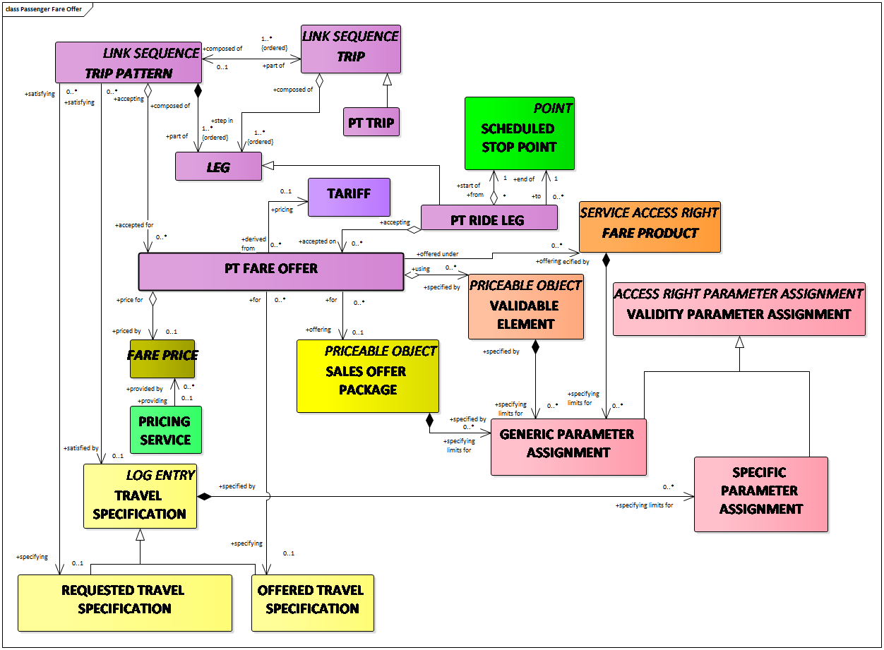
A PT FARE OFFER describes a FARE PRODUCT and its PRICE available for a particular PT TRIP or PT RIDE LEG.
For further explanations of the concepts related to the fares see EN12896-5.
Passenger information equipment
Delivery of passenger information through any form of device is described by the entity PASSENGER INFORMATION EQUIPMENT (a generic class of information device), which may be passive (for example a printed timetable), active (for example a display), or interactive (for example a kiosk terminal supporting trip planning).
A LOGICAL DISPLAY is a set of data that can be assembled for assignment to a physical PASSENGER INFORMATION EQUIPMENT or to a logical channel such as web or media.
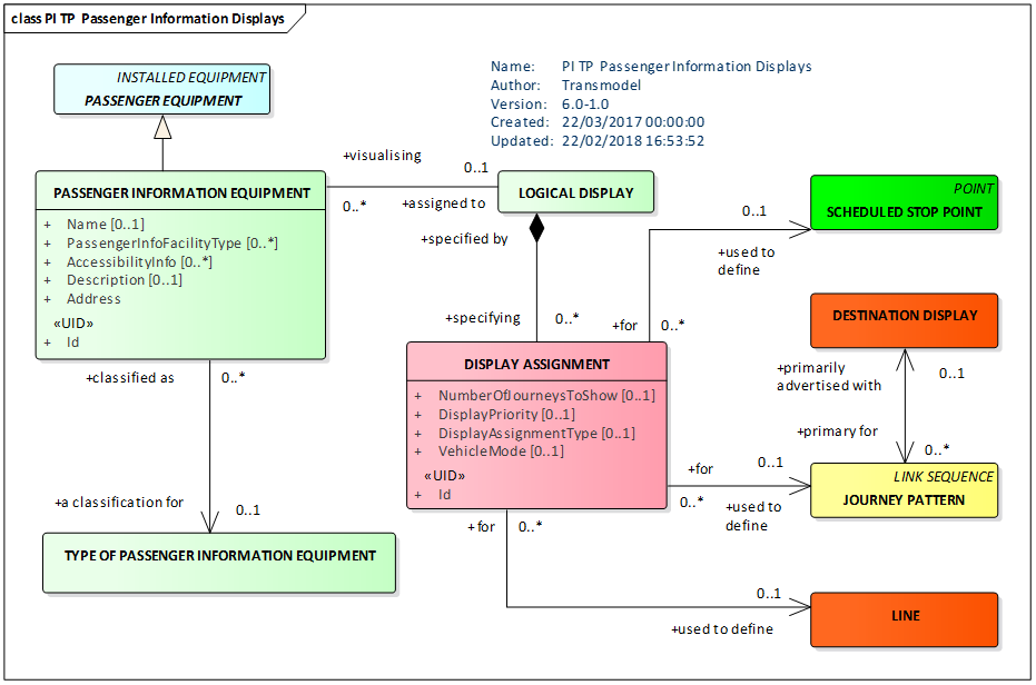
For more detailed discussion see EN12896-2.
Passenger Information requests
The Query Model uses a common framework comprising an abstract query made up of a request/response pair. It describes common query constructs used by all the different query types and provides an abstract template which can be populated by specific requests.
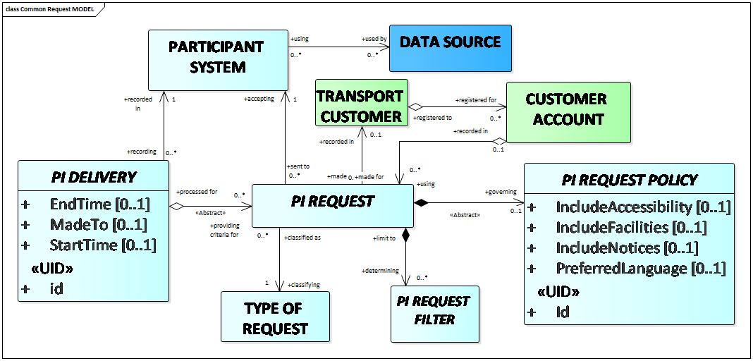
An Informative part of EN 12896-6 provides examples of Passenger Information (PI) REQUEST Models and indicate how the Transmodel data elements relate to APIs and web services that deliver transport data to the end user, for example journey planners, fare engines, etc. The models give guidance as to which Transmodel elements are relevant for typical passenger information queries, and to identify useful query criteria.
The figure below presents different types of PI REQUESTs and PI DELIVERies considered (see the Informative Annex E of EN 12896-6).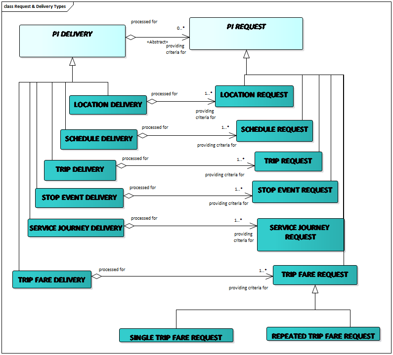
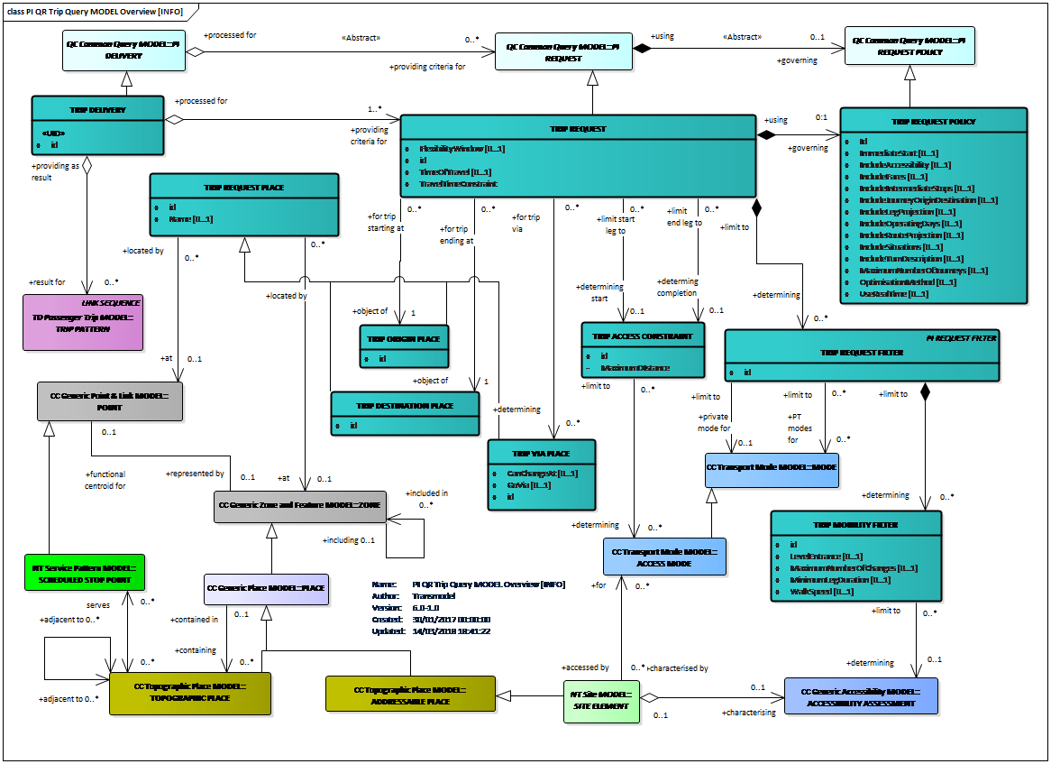
A TRIP REQUEST is used to request trip plans from a journey planning engine. The Trip Request can be used both for single-trips and for multi-point trips that go via several way points.
Transmodel gives an indicative set of parameters commonly found in trip planners, but others are possible and might be added to the filters to select or bias the results.
Below is an example of a Trip Query Model and the associated TRIP DELIVERY providing as result one or more TRIP PATTERNs.
Annex D of EN12896-6 provides a table with (approximate) equivalences between:
- the SIRI (Service Interface for Real-time Information, EN 15531 series) functional services
- the OADJP (Open API for Distributed Journey Planning, CEN/TS 17118:2017) functional services
and the Transmodel Request model.